Precise Infrared Imaging for Printed Circuit Board Fault Detection
Infrared Camera: A Time-Saving Solution for Troubleshooting PCB
Detecting Power and Ground Shorts on Printed Circuit Boards: A Challenging Task
Power-to-ground shorts on multi-layer printed circuit boards (PCBs) are a common and challenging issue to diagnose without damaging the board. Applying current to locate the short can result in permanent damage, which is unacceptable, especially for expensive or unique prototype boards.
Technicians and engineers traditionally use non-destructive methods to locate these shorts. They start by visually inspecting the PCB under good lighting or with a magnifying glass, looking for solder bridges, damaged components, or foreign materials that could be causing the short. If no obvious signs are found, a multimeter is used for further testing.
To perform a continuity test, the multimeter is set to continuity or diode test mode. The probes are placed on two points to test for shorts. The multimeter sends a low-voltage current through the circuit and measures the resistance. A very low resistance (typically less than a few ohms) indicates a continuous path for current flow, suggesting the presence of a short.
Locating the lowest voltage point on the board can help find the short, but this method may not be effective if the power and ground planes have resistances too small to produce a readable voltage. This challenge is exacerbated when the power planes are located in the board’s internal layers, which are inaccessible to test probes.
Other testing procedures, such as using an automated PCB tester with an oscilloscope to check signals, can locate the fault but require expensive tools, expertise, and time that may only sometimes be available.
Detecting Hidden Faults in PCB and IC Assemblies with Infrared Imaging
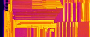
Thermographic inspection of electronic components and assemblies is an established procedure for failure detection and quality management, applicable from the development of initial prototypes to serial production. This method effectively detects various issues, such as hotspots and atypical temperature distributions on the surfaces of printed circuit boards, integrated circuits, and multichip modules. It identifies abnormal contact resistances, hidden cracks in joints, power losses due to RF mismatch, incorrect thermal connections of heat sinks, short circuits, and soldering defects like cold solder joints.
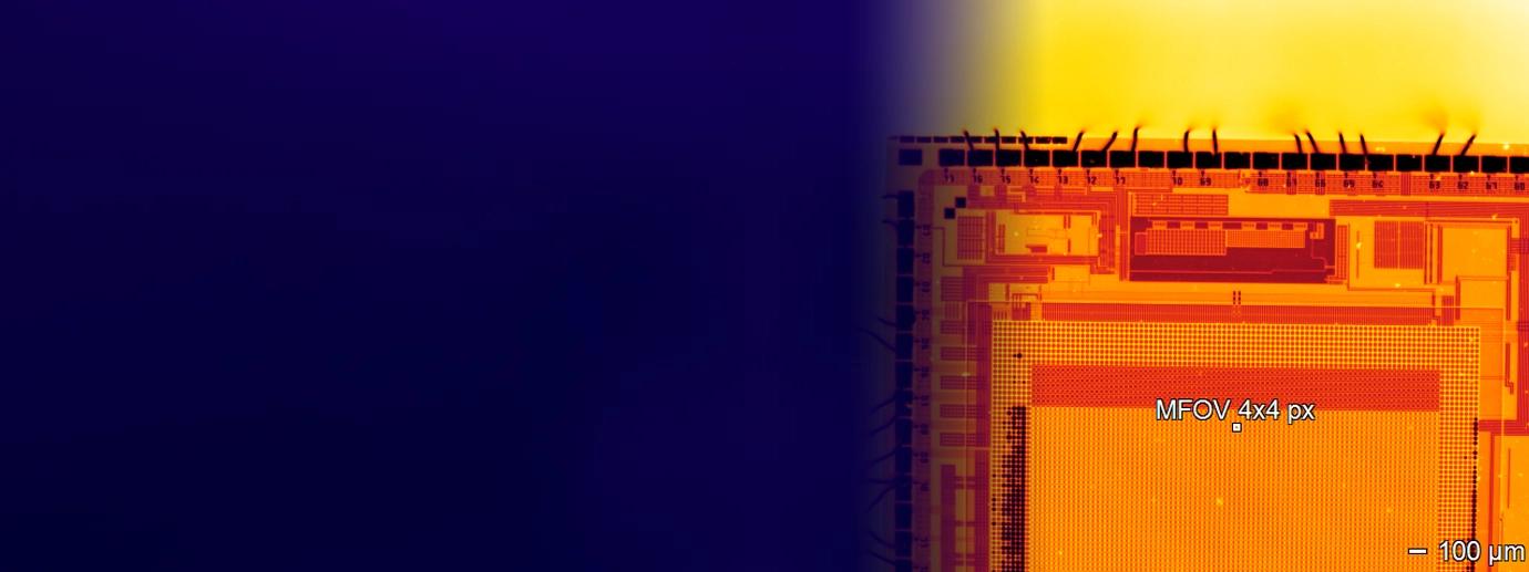
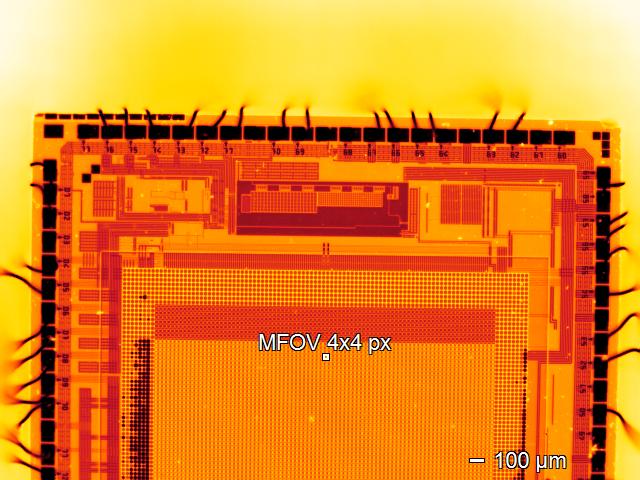
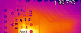
Short circuits on a PCB generate heat due to excessive current flow through unintended low-resistance paths. When a short circuit occurs, the electrical resistance drops significantly, causing a surge in current according to Ohm’s law (I = V/R). This increased current flow leads to rapid energy dissipation as heat, potentially damaging components and degrading board materials. An infrared camera can locate these hot spots, which generate significant heat. Starting with the lowest current makes it possible to identify the short circuit before it causes further damage. This method aids in early fault detection, preventing potential non-repairable damage to the PCB and its components.
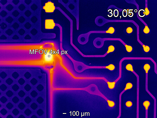
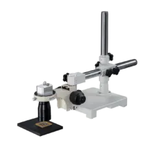
An IR microscope can be employed to identify the smallest issues. The infrared microscope will resolve short as small as 8 µm. This allows inspection of the finest SMD parts or even unpacked SMD components.
High Performance PI 640i with Dual Optics or Affordable Optris Xi 400 IR Camera
The increasing demand for smaller, more efficient, and reliable electronic components and systems necessitates thermal inspection tools that support critical decisions throughout the product development cycle. As the electronics industry focuses on reducing size and power consumption, infrared cameras with mid-range spatial resolution are essential for detecting faults in small devices and connections.
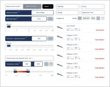
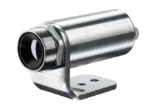
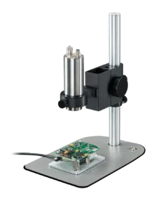
For effective fault detection, a mid-range resolution camera (320 x 240 or better) with a pixel count of at least 75,000 elements is recommended as an entry-level solution. In the Optris product line, the Xi400, available in several optic variants, is frequently used for PCB fault detection. Selecting a camera with the appropriate optic and measurement field of view (MFOV) resolution is crucial for accurate target measurement.
The ability to detect temperature rises on tiny targets with an infrared camera depends on the size and number of pixels the camera can focus on the small target. If the target is smaller than a single pixel, the temperature increase will be muted by the cooler surrounding temperatures, making the fault harder to locate and leading to inaccurate temperature measurements. The IR camera optics are equally important when detecting small temperature rises on electronic devices; high pixel counts are ineffective if the pixels cannot be focused on a small area.
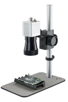
The optimal infrared camera system for fault detection in various electronic applications includes a high-resolution infrared camera (640 x 480) and at least two optics for quick infrared scans on large boards and detailed studies of faults on small devices. High-resolution thermal cameras with switchable calibrated optics and microscope options are the best choice for PCB fault detection.
Recommended Products


Other Electronics Applications

Talk to us about your IR Temperature Measurement Requirements
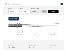
There are over 300 different pyrometer variants to choose from in the Optris infrared pyrometer portfolio each optimized for material, spot size, distance from the target, and environmental conditions. Fortunately, there is a trained engineer to phone or chat with to guide you through the process of choosing the perfect infrared sensor for your application.
The same support is available for the extensive IR camera product line.