
Electronics Design Validation through Infrared Measurements
Infrared Camera Reveals True Temperatures of Electronic Test Equipment, Outperforming Contact Thermocouples
Reliability Challenges in Test Equipment: Overheating PCB Components Under Investigation
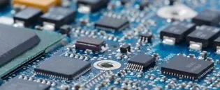
A manufacturer of electronic test equipment is experiencing reliability issues with its waveform analyzer, which is suspected to be caused by overheating components on one of the printed circuit boards (PCBs) within the chassis.
Comprehensive research is conducted on all electronic components on the suspect board to ascertain their maximum operating temperatures. The board is then mounted on a test stand and powered to replicate the conditions during processor-intensive use. Key components are measured with a contact thermometer to determine if any are operating above their maximum temperatures. While all are within their specified limits, several are found to be operating close to their maximum temperatures.
The issue with using thermocouples for temperature measurement on very small structures, such as an surface-mount device (SMD), is that they need to reflect the true temperature of the electronics accurately. For small PCB components, the thermal mass is quite small. Compared to these small SMD components, a thermocouple has enough thermal capacity to influence the component’s temperature while being tested. The thermocouple and its wiring draw heat away from the electronics component, resulting in lower temperature readings than the actual temperature of the SMD component without the thermocouple. Consequently, this leads to the measurement of smaller temperature amplitudes in static conditions and inaccurate thermal dynamics readings.
It is concluded that temperature testing within the equipment chassis is necessary to account for the impact of internal temperatures in an enclosed casing on component temperatures. Remote temperature measurements are deemed challenging due to potential line-of-sight obstructions caused by the equipment enclosure.
Reliability Challenges in Test Equipment: Overheating PCB Components Under Investigation
A manufacturer of electronic test equipment is experiencing reliability issues with its waveform analyzer, which is suspected to be caused by overheating components on one of the printed circuit boards (PCBs) within the chassis. Comprehensive research is conducted on all electronic components on the suspect board to ascertain their maximum operating temperatures. The board is then mounted on a test stand and powered to replicate the conditions during processor-intensive use.
Key components are measured with a contact thermometer to determine if any are operating above their maximum temperatures. While all are within their specified limits, several are found to be operating close to their maximum temperatures.
The issue with using thermocouples for temperature measurement on very small structures, such as an surface-mount device (SMD), is that they need to reflect the true temperature of the electronics accurately. For small PCB components, the thermal mass is quite small. Compared to these small SMD components, a thermocouple has enough thermal capacity to influence the component’s temperature while being tested. The thermocouple and its wiring draw heat away from the electronics component, resulting in lower temperature readings than the actual temperature of the SMD component without the thermocouple. Consequently, this leads to the measurement of smaller temperature amplitudes in static conditions and inaccurate thermal dynamics readings.
It is concluded that temperature testing within the equipment chassis is necessary to account for the impact of internal temperatures in an enclosed casing on component temperatures. Remote temperature measurements are deemed challenging due to potential line-of-sight obstructions caused by the equipment enclosure.
Optimizing Temperature Measurements in Electronic Enclosures with Infrared Technology
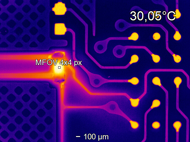
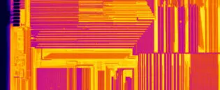
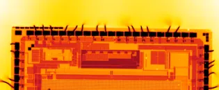
In general, the thermographic inspection of electronic components and assemblies is an established test procedure for failure detection and quality management, from developing initial prototypes to serial production. This method detects various issues, such as hotspots and atypical temperature distributions on the surface of printed circuit boards, integrated circuits, and multichip modules. It will identify increased abnormal contact resistances, hidden cracks in joints, power losses due to RF mismatch, incorrect thermal connections of heat sinks, short circuits, and soldering defects such as cold solder joints.
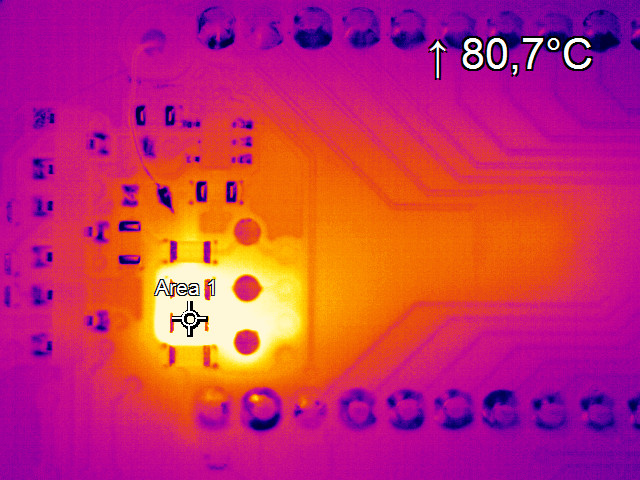
In this application, an infrared camera, used with IR transmissive materials, accurately assesses the temperatures of all critical board components while replicating a typical operating environment within the equipment enclosure (chassis). A top cover section is removed and tested with several infrared transmissive materials, starting with Saran wrap. The Saran wrap proves highly transmissive in the infrared region, attenuating less than 10% of the signal. Still, it flutters when the instrument fan is engaged, and its durability poses some problems. Zinc Selenide is considered the best solution due to its durability and ability to permit visual observation. Still, the cost of a window large enough to cover the entire PC board is prohibitive. Calcium Fluoride infrared windows, commonly used for electrical switchgear infrared testing, are the best solution. Although their infrared transmission is less than that of ZnSe, this can be accounted for when producing accurate measurements. The metal housings of the infrared windows make them easy to mount into the metal enclosure, and their affordability allows several windows to gather data on all key components. Two devices are immediately determined to be operating over temperature due to their mounting locations next to other heat-producing devices and inadequate airflow to disperse heat from hot devices.
Infrared Camera Outperforms Contact Thermocouple in Measuring Thermal Electronic Components
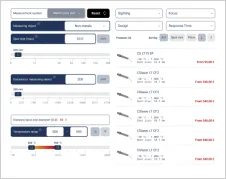
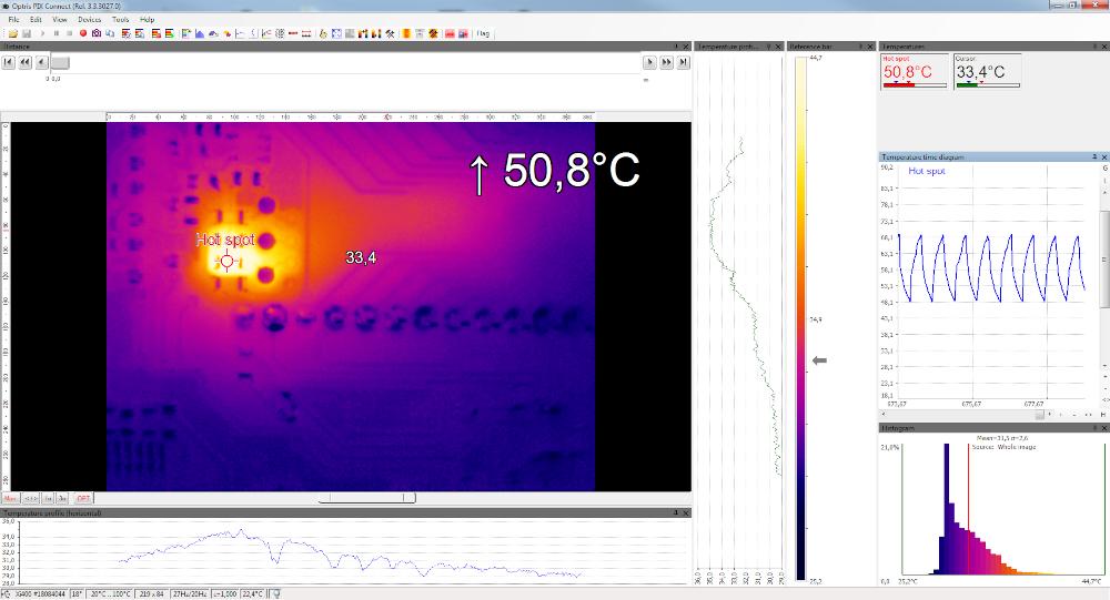
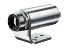
The Optris Xi 400 is small and easy to mount on a rail system positioned both above and below the equipment chassis where IR windows are placed. It is angled to optimize the line of sight to the important components. PIX Connect software makes it easy to set up spots or small areas to measure the hottest pixel inside the enclosed areas, with no limit on the number of components that can be tracked. Time vs. temperature data is simple to collect and store in CSV files for later study and analysis. The “Hot Spot” tool in the software is useful for identifying the hottest location on the board.
Measuring and accounting for infrared transmission through the windows is critical for accurate temperature measurement, and the transmissivity setting in PIX Connect makes it easy to measure the transmission by comparing the temperature of a target without a window to the temperature with the IR window in place, adjusting the transmission factor until the temperatures match. It is also determined that placing a contact thermocouple on a small device can lower the temperature of the device by conducting heat away from it, making the measurements from the IR camera more accurate than those made with a thermocouple. Measurements on ceramic and all polymer-based materials are accurate, but carbon black needs to be applied to metal cans to improve surface emissivity.
Recommended Products


Other Electronics Applications

Talk to us about your IR Temperature Measurement Requirements
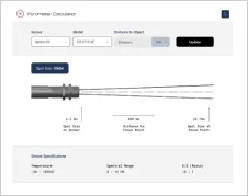
There are over 300 different pyrometer variants to choose from in the Optris infrared pyrometer portfolio each optimized for material, spot size, distance from the target, and environmental conditions. Fortunately, there is a trained engineer to phone or chat with to guide you through the process of choosing the perfect infrared sensor for your application.
The same support is available for the extensive IR camera product line.