Enhancing Temperature Monitoring in High-Voltage Electrical Systems
Non-contact Temperature Measurement Solutions for High-Voltage System and Busbar Monitoring
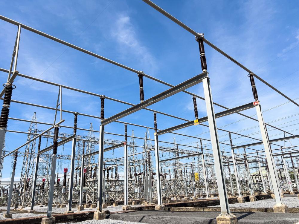
Challenges and Importance of Temperature Monitoring in High-Voltage Electrical Systems
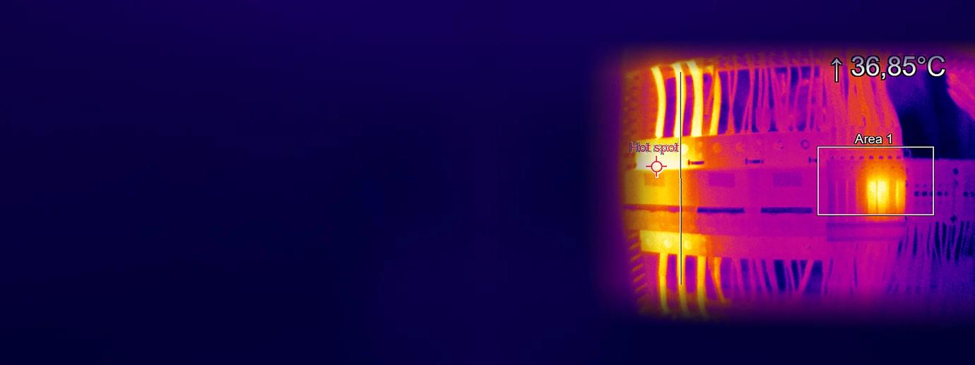
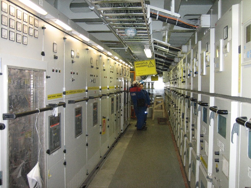
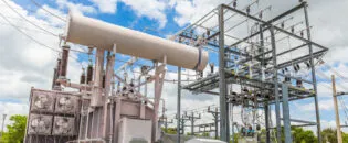
The temperature of electrical connections in power distribution systems is a crucial indicator of their condition. As connections degrade, their resistance increases, leading to a rise in temperature. This rise can cause further damage and pose a significant risk of fire or explosion. Neglecting continuous temperature monitoring can lead to costly downtime and unexpected equipment failures, potentially resulting in safety hazards. Large industrial sites typically house electrical switchgear, transformers, and panels in dedicated rooms, where faults can develop gradually over time or rapidly due to sudden component failures. Continuous temperature monitoring is essential for preventing these risks and planning preventative maintenance.
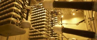
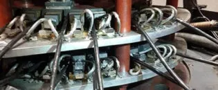
Several factors can generate heat, such as overload, phase imbalance, power factor issues, corrosion, and poor electrical connections. This heat generation not only indicates energy loss and power wastage but can also reduce the lifespan of equipment by up to 85%. These conditions may develop slowly or result from catastrophic faults. Inside switchgear cabinets, power is transferred by copper busbars bolted together at connections, which are particularly susceptible to failure. An increase in joint temperature can be an early sign of deterioration, detectable through continuous temperature monitoring using sensors.
Temperature measurement in high-voltage (HV) environments presents significant challenges concerning personal safety. Conventional electrical measurement technologies, such as thermocouples, RTDs, and NTCs, address these challenges through highly isolated measurement electronics, sensors, and specially insulated cables. However, using electrical sensors in HV environments has drawbacks. Both instrumentation and maintenance require a qualified electrician. The strong insulation of cables and the diameters of conventional sensors can inadmissibly affect HV objects during installation, such as when drilling holes. Thick cable insulation also complicates multi-channel applications in tight areas. Moreover, in the event of a sensor failure, the entire cable, sensor, and connector must be replaced as a single, encapsulated, and tested unit. Despite their isolation, conventional sensors’ signal quality can be compromised by electromagnetic disturbances (EMC), electrostatic discharges (ESD), and high electrical potentials commonly found in power electronics (inverters).
Rethinking Maintenance Procedures Using Noncontact IR thermometers in High-Voltage Environments
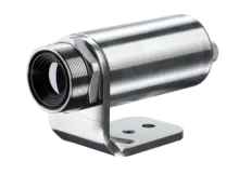
Contact temperature measurement can be dangerous, time-consuming, and costly, making non-contact infrared (IR) sensors necessary. Low-cost IR sensors, permanently mounted inside switchgear cabinets, are designed for condition monitoring and provide early warnings for preemptive maintenance. However, they are not intended for emergency shutdowns, fire detection, or as primary safety measures.
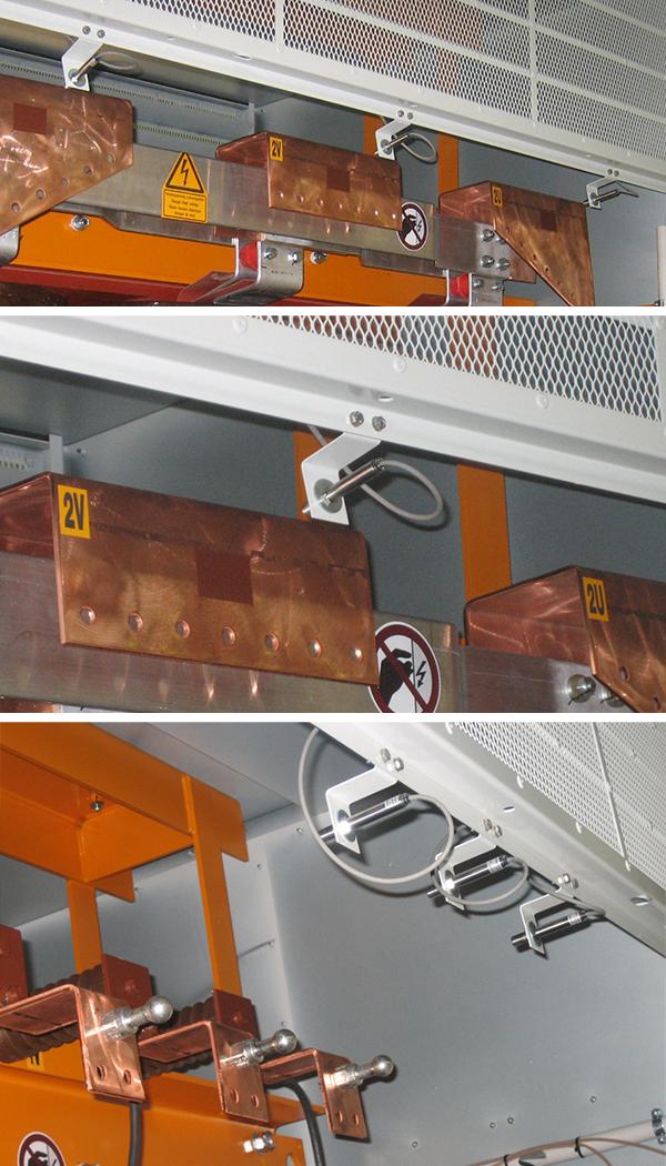
Accurate temperature measurements are crucial for effective maintenance and safety. To ensure this accuracy, the busbar surface should be prepared at the measurement location to minimize reflectivity. This can be achieved by painting, coating, or shrink-wrapping the surface. Alternatively, exploiting the cavity effect of infrared light by placing the measurement spot in a cavity or on edges can also help. The usual copper surface of busbars, an Optris emissivity sticker, can be used to increase emissivity.
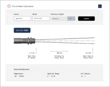
Optical resolutions for these sensors range from 2:1 to 22:1, allowing safe sensor placement within the cabinet at a distance from the busbar to avoid flashover and electromagnetic interference (EMI). Wide-angle 2:1 optics are optimal at short distances, while narrower 22:1 optics are suitable for higher voltages, enabling longer measurement distances. Focused optics are available for measuring narrow or thick busbars edge-on.
The sensor is positioned safely from the busbar to avoid the risk of an electric arc and measures the surface temperature within a small spot. The measured spot size depends on the chosen optics and the measurement distance, with half the busbar width being the recommended spot size. The sensor head and mounting bracket do not require special insulating materials for mounting to the equipment structure.
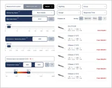
Output signals from the sensors are typically fed into a programmable logic controller (PLC) or distributed computer control system. These systems use the data for alarming and trending purposes, providing a comprehensive view of the switchgear’s condition over time.
Cost-Effective Temperature Monitoring of Busbars with CS LT Pyrometers on Container Ships
Busbars, with their versatile applications, are essential components in electrical systems, providing safe high-voltage (HV) connections over shorter distances. They are widely used across various sectors, mainly where flexible power distribution is crucial. Busbars connect high-voltage equipment in electrical switchyards and low-voltage equipment in battery banks, making them prominent in the automotive and defense sectors. Joints between high-current bus sections often have precisely machined matching surfaces that are silver-plated to reduce contact resistance.
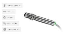
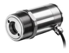
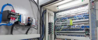
In this particular application on a container ship’s electrical utility station, several CS LT pyrometers have been employed inside a switching cabinet to monitor the temperature load of the busbars. The busbars are critical for maintaining reliable power distribution on the ship, ensuring that various systems operate smoothly and efficiently. The use of CS LT pyrometers for monitoring provides real-time data on the temperature of the busbars, allowing for immediate detection of any anomalies that could indicate potential issues such as overheating or excessive load.
The simple alarming function of the CS LT pyrometers, which includes a digital output, forwards information to a centralized logical unit. This feature ensures that any temperature deviations are promptly reported, enabling quick responses to prevent any possible failures or safety hazards. This retrofit installation has made traditional spot-check monitoring with handheld IR guns obsolete in tight and hard-to-reach locations, ensuring time savings, easing workforce limitations, and mitigating safety risks. The continuous monitoring capability also enhances the overall safety and reliability of the electrical system on the container ship.
The CS LT pyrometer, a low-budget sensor designated for OEM solutions, has proven to be cost-effective for such applications. Its implementation not only improves operational efficiency but also extends the lifespan of the busbars by preventing thermal stress and potential damage. This solution exemplifies how modern technology can be leveraged to enhance traditional electrical systems, providing better performance and increased safety.
Recommended Products


Other Condition Monitoring Applications


Talk to us about your IR Temperature Measurement Requirements
There are over 300 different pyrometer variants to choose from in the Optris infrared pyrometer portfolio each optimized for material, spot size, distance from the target, and environmental conditions. Fortunately, there is a trained engineer to phone or chat with to guide you through the process of choosing the perfect infrared sensor for your application.
The same support is available for the extensive IR camera product line.